
TM 5-3990-263-13&P
FIELD MAINTENANCE
TRANSLOAD ROLLER REPLACEMENT
INITIAL SETUP:
References
Tools and Special Tools
Tool Kit, General Mechanics: Automotive
Parts Manual (WP 0073, Figure 8)
(WP 0078, Table 2, Item 2)
Materials/Parts
Equipment Condition
Cotter Pin (WP 0082, Table 1, Item 37)
Load removed from BAP. (WP 0008)
Lockwasher (WP 0082, Table 1, Item 50)
BAP unloaded from vehicle. (WP 0006)
Spring Pin (WP 0082, Table 1, Item 49)
Personnel Required
(2)
REMOVAL
NOTE
This procedure is for either curb-side or road-side transload roller replacement. Road side is
shown.
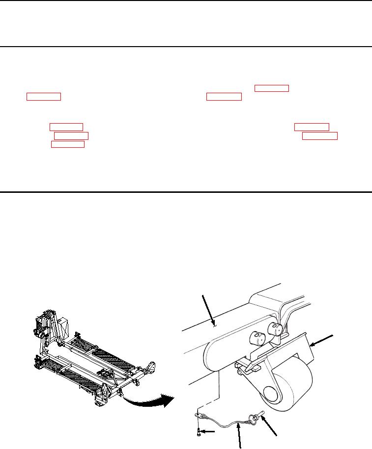
1.
Remove-quick release pin (Figure 1, Item 1) from transloader bracket (Figure 1, Item 2). Remove screw (Figure
1, Item 3) and lanyard (Figure 1, Item 4) from BAP frame (Figure 1, Item 5).
5
2
3
1
4
Figure 1.
Quick Release Pin Removal.
2.
Remove cotter pin (Figure 2, Item 6) from straight pin (Figure 2, Item 7). Discard cotter pin.
03/15/2011Rel(1.8)root(maintwp)wpno(M04044)