• Home
  • Download PDF
  • Order CD-ROM
  • Order in Print
Figure 4. Transload Roller Pin Installation.
REFLECTOR REPLACEMENT

Parts Manual For Pallet, Adapter, Bridge M15 Page Navigation
  335    336    337    338    339  340  341    342    343    344    345  
img
.
TM 5-3990-263-13&P
0049
INSTALLATION - Continued
5
2
3
1
4
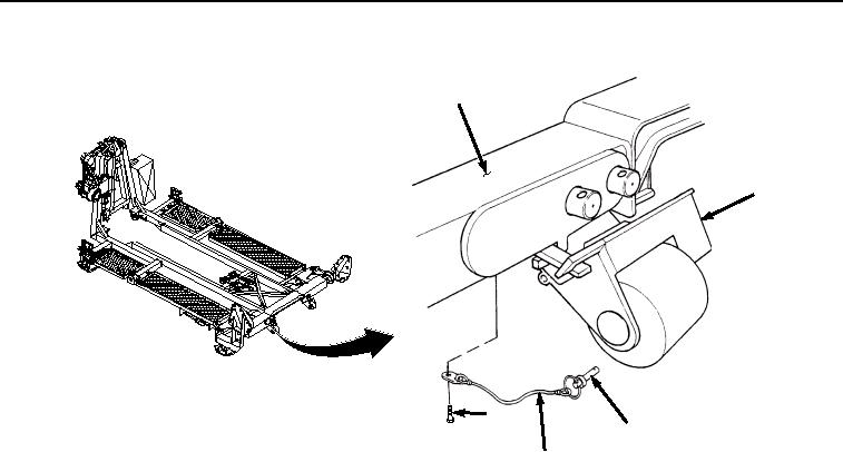
Figure 6. Quick Release Pin Installation.
7.
Place roller (Figure 6, Item 8) and transloader bracket (Figure 6, Item 2) in stowed position, and insert quick-
release pin (Figure 6, Item 1) in frame (Figure 6, Item 5).
END OF TASK
END OF WORK PACKAGE
0049-5/6 blank
03/15/2011Rel(1.8)root(maintwp)wpno(M04044)


Privacy Statement
Press Release
Contact

© Copyright Integrated Publishing, Inc.. All Rights Reserved.