
TM 5-3990-263-13&P
FIELD MAINTENANCE
WINCH FRAME LOCKING LEVER OUTBOARD RETAINER BLOCKS FIELD REPLACEMENT
INITIAL SETUP:
Materials/Parts (cont.)
Tools and Special Tools
Rod, Welding MG600 (WP 0081, Table 1, Item
Welder, Portable (WP 0078, Table 2, Item 1)
24) Qty: 1
Hand Grinder, Portable (WP 0078, Table 2, Item
1)
Shim Stock, 0.040 in. (WP 0082, Table 1, Item 1)
Clamps (WP 0078, Table 2, Item 1)
Qty: 1
Materials/Parts
References
Block, Retainer (WP 0081, Table 1, Item 1)
Parts Manual (WP 0073, Figure 12)
Rod, Welding 336 or 340 (WP 0081, Table 1, Item
25) Qty: 1
Equipment Condition
Load removed from the BAP. (WP 0008)
BAP removed from the CBT. (WP 0006)
REMOVAL
NOTE
Use MG600 1/16 in. filler rod if using a TIG welder.
Use 336 or 340 welding rod if stick welding.
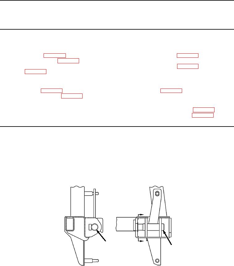
Grind off any remaining weld or broken retainer block from locking pin (Figure 1, Item 1).
A
1
A
1
VIEW A
Figure 1.
Winch Frame Locking Lever Outboard Retainer Blocks Field Removal.
END OF TASK
03/15/2011Rel(1.8)root(maintwp)wpno(M04111)