
TM 5-3990-263-13&P
0054
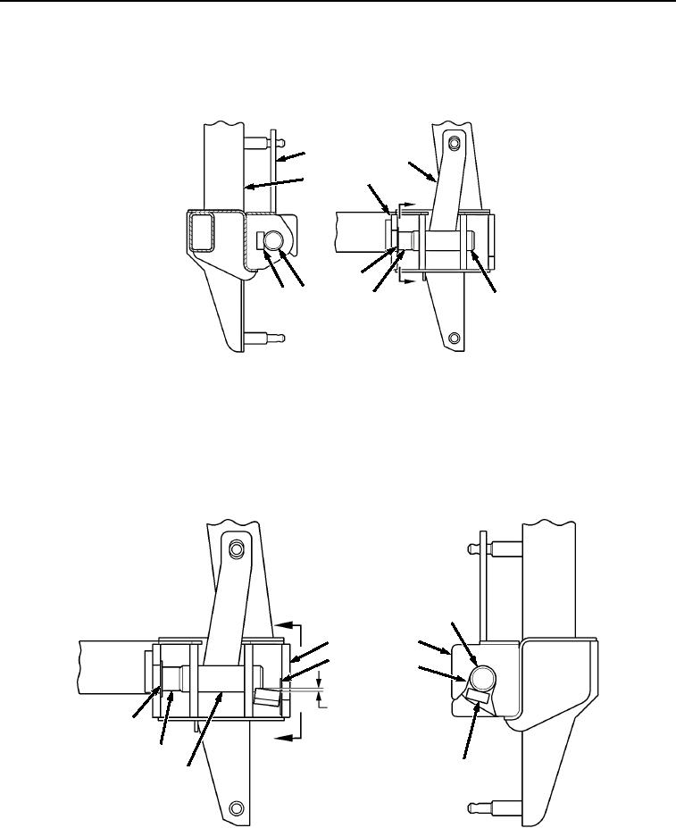
INSTALLATION
1.
Rotate locking lever (Figure 2, Item 2) to the up position. Inboard retainer block (Figure 2, Item 3) should be
to the back of locking pin (Figure 2, Item 1) and parallel with the winch frame (Figure 2, Item 4).
2
2
4
4
A
5
A
1
3
3
1
VIEW A
Figure 2.
Winch Frame Locking Lever Outboard Retainer Blocks Field Installation.
2.
Place a 0.040 in. (0.1016 cm) thick shim (Figure 2, Item 5) between end of inboard retainer block (Figure 2,
Item 3) and winch frame (Figure 2, Item 4) and clamp in place.
3.
Position outboard retainer block (Figure 3, Item 6) on the locking pin (Figure 3, Item 1) so that outboard retainer
block is centered in the outboard lock beam opening (Figure 3, Item 7).
B
1
4
4
5
7
1/8 in. TO 3/16 in.
OFF SQUARE
5
BEFORE WELDING
B
3
6
1
VIEW B
Winch Frame Locking Lever Outboard Retainer Blocks Field Installation.
Figure 3.
03/15/2011Rel(1.8)root(maintwp)wpno(M04111)