TM 5-3990-263-13&P
0054
INSTALLATION - Continued
4.
Pre-stress outboard retainer block (Figure 3, Item 6) 1/8 in. (0.3175 cm) to 3/16 in. (0.47625 cm) out of square
off the end of locking pin (Figure 3, Item 1) to counter pull of the weld.
5.
Place a 0.040 in thick shim (Figure 3, Item 5) between end of outboard retainer block (Figure 3, Item 6) and
winch frame (Figure 3, Item 4) and clamp in place.
6.
Pre-heat locking pin (Figure 3, Item 1) to 475F (246C).
7.
Tack weld outboard retainer block (Figure 3, Item 6) on back corners.
8.
Weld root pass on sides of retainer block from back to front.
9.
Build up weld from side to side until just over flush. All weld passes should be made from back to front.
10.
Build up weld across front of retainer block until just under flush.
11.
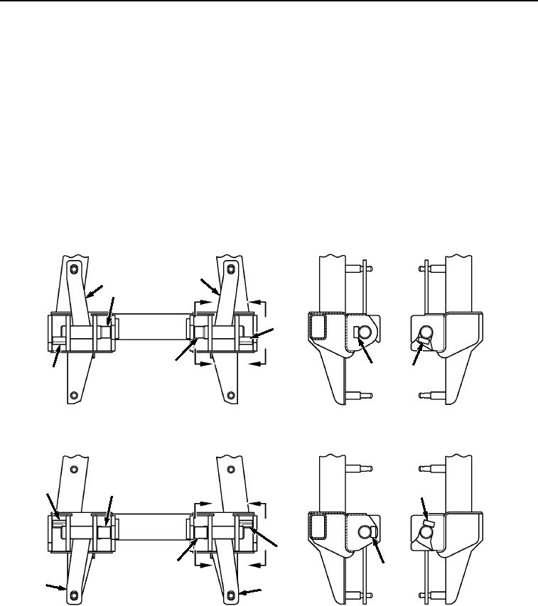
Check that locking levers (Figure 4, Item 2) move freely to upper and lower lock positions. Check that inboard
retainer blocks (Figure 4, Item 3) and outboard retainer blocks (Figure 4, Item 6) are in the correct positions.
2
2
3
A
B
6
3
3
6
6
B
A
UP POSITION
VIEW A
VIEW B
6
3
6
C
D
6
3
3
C
D
2
2
VIEW C
VIEW D
DOWN POSITION
Figure 4. Winch Frame Locking Lever Outboard Retainer Blocks Field Installation.
END OF TASK
END OF WORK PACKAGE
03/15/2011Rel(1.8)root(maintwp)wpno(M04111)

