
TM 5-3990-263-13&P
0055
REMOVAL - Continued
2
4
5
6
1
3
9
9
7
8
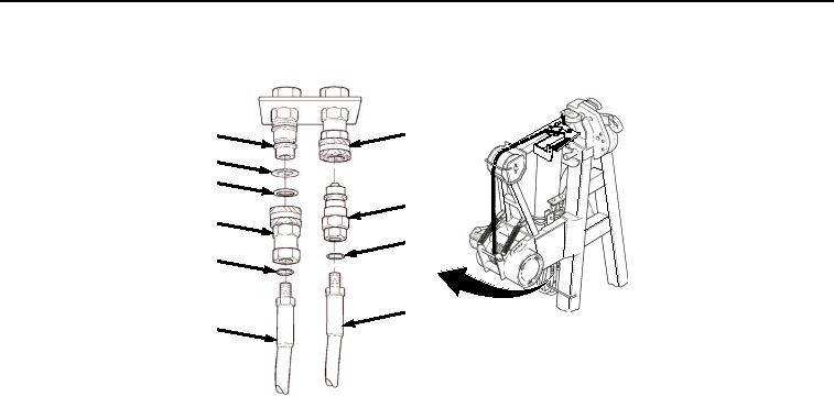
Figure 1. Winch Quick Disconnect Removal.
2.
Remove female quick-disconnect coupling half (Figure 1, Item 3) from dummy male quick-disconnect coupling
half (Figure 1, Item 4).
3.
Remove backup ring (Figure 1, Item 5) and preformed packing (Figure 1, Item 6) from female quick-disconnect
coupling half (Figure 1, Item 3). Discard backup ring and preformed packing.
4.
Remove male quick-disconnect coupling half (Figure 1, Item 1) from hose (Figure 1, Item 7).
5.
Remove female quick-disconnect coupling half (Figure 1, Item 3) from hose (Figure 1, Item 8). Remove two
O-rings (Figure 1, Item 9) from male quick-disconnect coupling half (Figure 1, Item 1) and female quick-
disconnect coupling half (Figure 1, Item 3). Discard O-rings.
6.
Remove tube nut (Figure 2, Item 10) from hose connector (Figure 2, Item 11). Remove tube nut (Figure 2, Item
12) from hose connector (Figure 2, Item 13).
03/15/2011Rel(1.8)root(maintwp)wpno(M04049)