
TM 5-3990-263-13&P
0066
INSTALLATION - Continued
2.
Install rubber stop (Figure 5, Item 27) in bracket (Figure 5, Item 3) with screw (Figure 5, Item 26) and locknut
(Figure 5, Item 25).
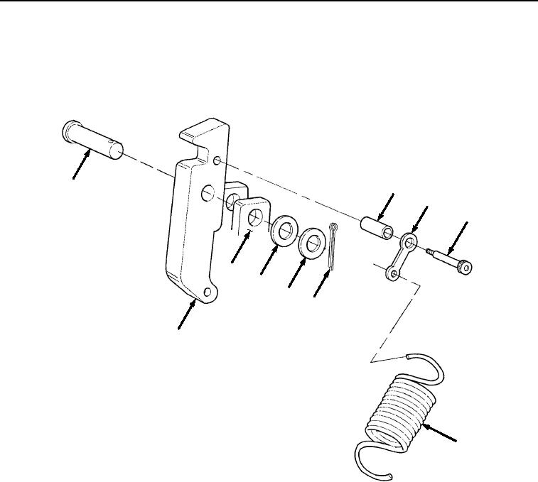
3.
Install spacer tube (Figure 6, Item 24) and spring extension (Figure 6, Item 22) on lock (Figure 6, Item 8) with
shoulder bolt (Figure 6, Item 23).
19
24
22
23
3
20
18
17
8
21
Figure 6. Front BAP Lock Installation.
4.
Install spring (Figure 6, Item 21) on bracket (Figure 6, Item 3) and spring extension (Figure 6, Item 22).
5.
Position lock (Figure 6, Item 8) in bracket (Figure 6, Item 3).
03/15/2011Rel(1.8)root(maintwp)wpno(M04077)