
TM 5-3990-263-13&P
FIELD MAINTENANCE
REMOTE CONTROL UNIT REPAIR
INITIAL SETUP:
Materials/Parts (cont.)
Tools and Special Tools
Lockwasher (WP 0082, Table 1, Item 40) Qty:
4
Soldering Gun (WP 0078, Table 2, Item 1)
Gasket (WP 0082, Table 1, Item 19) Qty: 1
Tool Kit, Electrical (WP 0078, Table 2, Item 1)
Tool Kit, General Mechanic's: Automotive
(WP 0078, Table 2, Item 2)
References
Respirator, Air Filtering
Parts Manual (WP 0073, Figure 26)
(WP 0078, Table 2, Item 4)
Materials/Parts
Equipment Condition
Cable Ties (WP 0081, Table 1, Item 2, 3)
Batteries disconnected (TM 9-2320-435-10 or TM
Tags, Identification (WP 0081, Table 1, Item 22)
9-2320-425-10). (WP 0076)
DISASSEMBLY
NOTE
Tag and mark wires, connectors, and harnesses prior to disassembly to ensure proper
assembly.
Remove cable ties as required.
1.
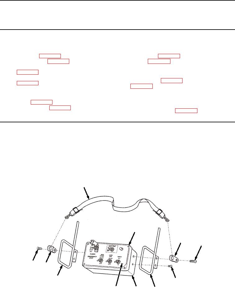
Remove neck strap (Figure 1, Item 1) from two neck strap brackets (Figure 1, Item 2).
1
3
2
6
6
2
8
7
4
5
8
Figure 1. Remote Control Unit Disassembly.
03/15/2011Rel(1.8)root(maintwp)wpno(M04101)