
TM 5-3990-263-13&P
0067
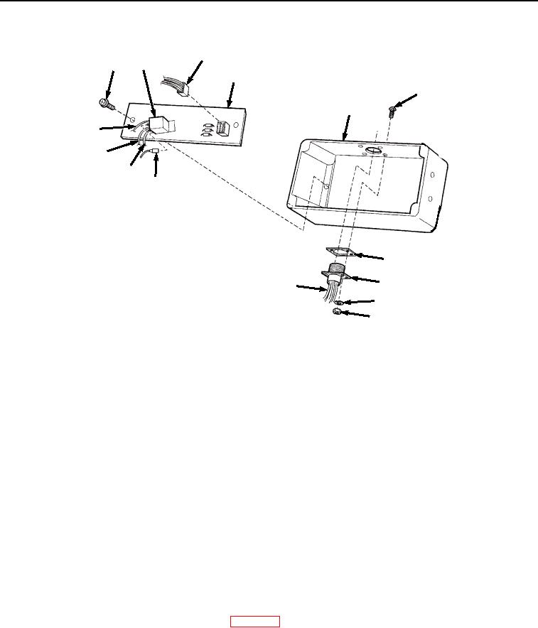
DISASSEMBLY - Continued
47
60
53
48
56
5
52
50
51
49
58
57
59
55
54
Figure 5. Remote Control Unit Disassembly.
19.
Remove spade connector (Figure 5, Item 49), spade connector (Figure 5, Item 50), spade connector (Figure
5, Item 51), and spade connector (Figure 5, Item 52) from relay (Figure 5, Item 53).
20.
Remove four nuts (Figure 5, Item 54), lockwashers (Figure 5, Item 55), screws (Figure 5, Item 56), connector
J9 (Figure 5, Item 57), and gasket (Figure 5, Item 58) from base (Figure 5, Item 5). Discard lockwashers and
gasket.
NOTE
Tag and mark all wires prior to disassembly to ensure proper assembly.
21.
Unsolder all wires (Figure 5, Item 59) from connector J9 (Figure 5, Item 57).
NOTE
Note position of circuit board prior to disassembly to ensure proper assembly.
22.
Remove two screws (Figure 5, Item 60) and circuit board (Figure 5, Item 48) from base (Figure 5, Item 5).
END OF TASK
CLEANING
Refer to General Maintenance Instructions (WP 0038) for general cleaning instructions.
END OF TASK
03/15/2011Rel(1.8)root(maintwp)wpno(M04101)