
TM 5-3990-263-13&P
0067
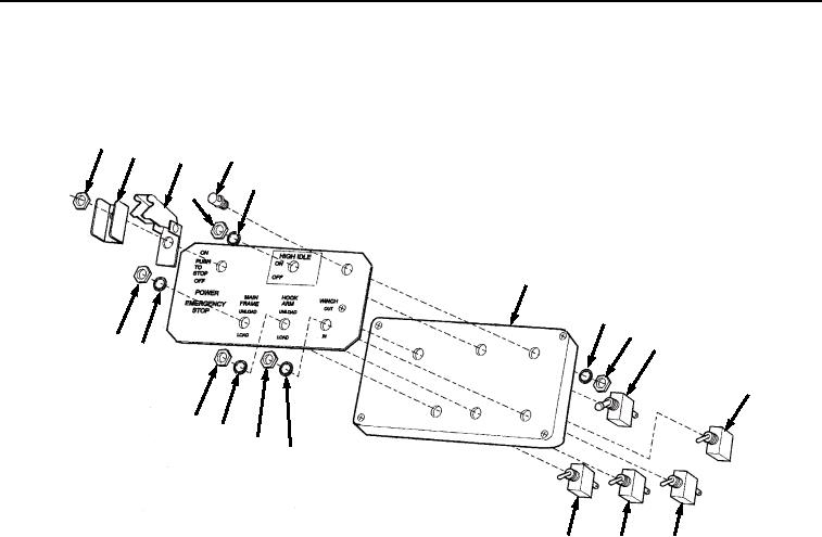
ASSEMBLY - Continued
6.
Install light (Figure 7, Item 31) in cover (Figure 7, Item 4) with lockwasher (Figure 7, Item 46) and nut (Figure
7, Item 45).
42
44
31
43
41
40
4
46
45
11
34
35
27
36
37
38
39
15
19
23
Figure 7. Remote Control Unit Assembly.
NOTE
Install switches as noted prior to disassembly.
7.
Install ON/OFF switch (Figure 7, Item 11), switch guard (Figure 7, Item 44), and snap cover (Figure 7, Item
43) on cover (Figure 7, Item 4) with nut (Figure 7, Item 42).
8.
Install HIGH IDLE switch (Figure 7, Item 27) in cover (Figure 7, Item 4) with lockwasher (Figure 7, Item 41)
and nut (Figure 7, Item 40).
9.
Install WINCH switch (Figure 7, Item 23) in cover (Figure 7, Item 4) with lockwasher (Figure 7, Item 39) and
nut (Figure 7, Item 38).
10.
Install HOOK ARM switch (Figure 7, Item 19) in cover (Figure 7, Item 4) with lockwasher (Figure 7, Item 37)
and nut (Figure 7, Item 36).
11.
Install MAIN FRAME load/unload switch (Figure 7, Item 15) in cover (Figure 7, Item 4) with lockwasher (Figure
7, Item 35) and nut (Figure 7, Item 34).
12.
Install brown wire (Figure 8, Item 33) on cover (Figure 8, Item 4) with screw (Figure 8, Item 32).
03/15/2011Rel(1.8)root(maintwp)wpno(M04101)