
TM 5-3990-263-13&P
0067
ASSEMBLY - Continued
1
3
2
6
6
2
8
7
4
5
8
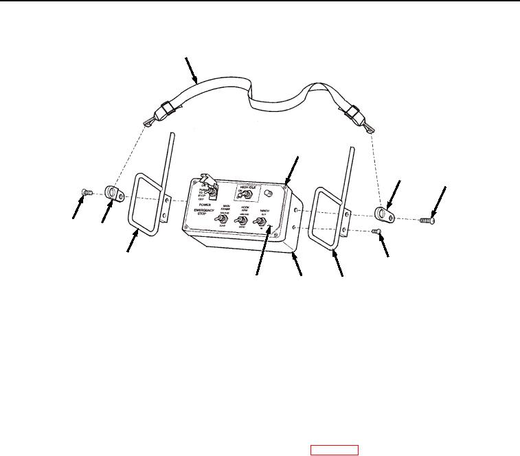
Figure 10. Remote Control Unit Assembly.
20.
Install two neck strap brackets (Figure 10, Item 2) on base (Figure 10, Item 5) with two screws (Figure 10, Item
6).
21.
Install cover (Figure 10, Item 4) on base (Figure 10, Item 5) and tighten four screws (Figure 10, Item 3).
22.
Install neck strap (Figure 10, Item 1) on two neck strap brackets (Figure 10, Item 2).
END OF TASK
FOLLOW-ON MAINTENANCE
Connect batteries (TM 9-2320-435-10 or TM 9-2320-425-10). (WP 0076)
END OF TASK
END OF WORK PACKAGE
03/15/2011Rel(1.8)root(maintwp)wpno(M04101)