
TM 5-3990-263-13&P
0068
BRAKE HUB ASSEMBLY REMOVAL - Continued
8.
Remove seven spacer plates (Figure 1, Item 12), six brake spacer plates (Figure 1, Item 13), and brake spacer
(Figure 1, Item 14) from brake housing (Figure 1, Item 5).
END OF TASK
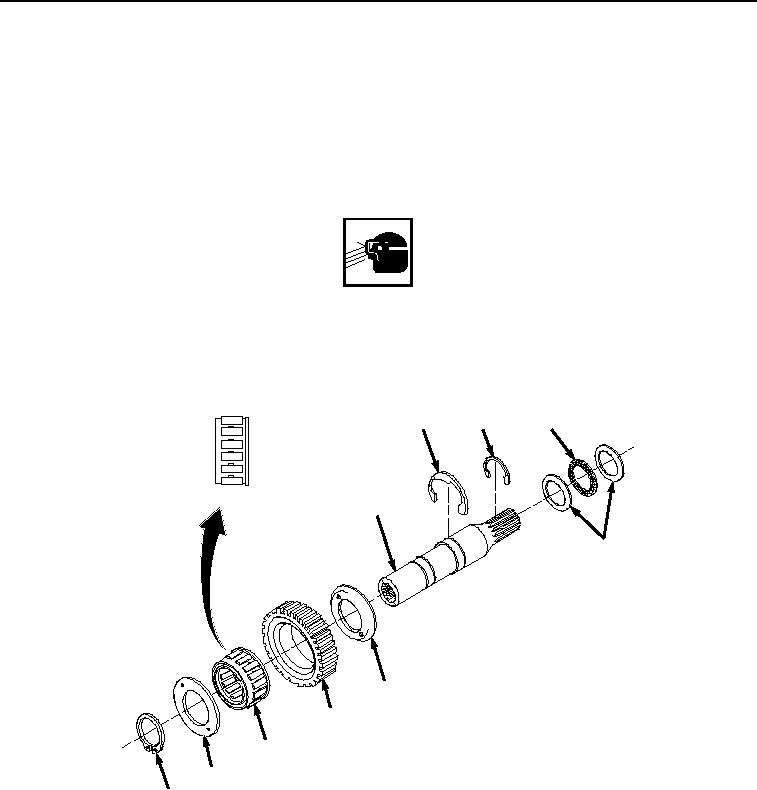
BRAKE HUB SUBASSEMBLY DISASSEMBLY
WARNING
Wear safety goggles and use caution when removing or installing springs, snaprings,
retaining rings, and other parts under spring tension. These parts are under tension and can
act as projectiles when released. Failure to comply may result in serious injury or death to
personnel.
1.
Remove snapring (Figure 2, Item 15) from motor drive shaft (Figure 2, Item 16).
20
21
23
16
22
17
18
19
17
15
Figure 2.
Brake Hub Subassembly Removal.
2.
Remove two clutch liners (Figure 2, Item 17) and brake hub (Figure 2, Item 18) from motor drive shaft (Figure
2, Item 16).
3.
Remove bearing (Figure 2, Item 19) from brake hub (Figure 2, Item 18).
03/15/2011Rel(1.8)root(maintwp)wpno(M05030)