
TM 5-3990-263-13&P
0068
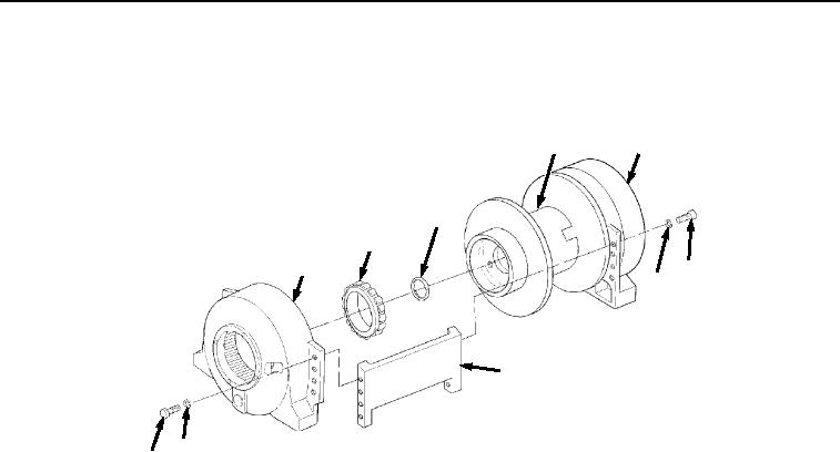
BRAKE HOUSING REMOVAL
1.
Remove 16 screws (Figure 4, Item 34), lockwashers (Figure 4, Item 35), and two tie bars (Figure 4, Item 36)
from brake housing (Figure 4, Item 5) and final housing (Figure 4, Item 26). Discard lockwashers.
37
26
38
39
5
34
35
36
35
34
Figure 4. Brake Housing Removal.
2.
With the aid of an assistant, remove brake housing (Figure 4, Item 5) from cable drum (Figure 4, Item 37).
NOTE
Cylindrical roller bearing comes apart with the brake housing, and the cylindrical roller race
remains in the cable drum. Perform Step (3) only if cylindrical roller bearing is damaged.
3.
Remove spacer (Figure 4, Item 38) and cylindrical roller bearing (Figure 4, Item 39) from brake housing (Figure
4, Item 5). Discard spacer.
END OF TASK
CABLE DRUM ASSEMBLY REMOVAL
1.
Remove oil seal (Figure 5, Item 40) from cable drum (Figure 5, Item 37). Discard oil seal.
03/15/2011Rel(1.8)root(maintwp)wpno(M05030)