
TM 5-3990-263-13&P
0068
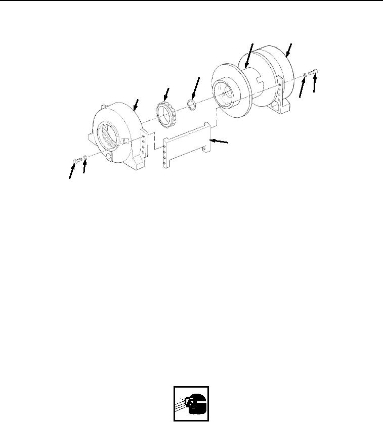
BRAKE HOUSING INSTALLATION - Continued
37
26
38
39
5
34
35
36
35
34
Figure 9.
Brake Housing Installation.
NOTE
Remove cylindrical roller race from cylindrical roller bearing before installing cylindrical
roller bearing.
Perform Step (2) only if cylindrical roller bearing was removed.
2.
Install cylindrical roller bearing (Figure 9, Item 39) on brake housing (Figure 9, Item 5) using an arbor press.
3.
With the aid of an assistant, install brake housing (Figure 9, Item 5) on cable drum (Figure 9, Item 37), ensuring
the two tie bars (Figure 9, Item 36) align from brake housing (Figure 9, Item 5) to final housing (Figure 9, Item
26).
4.
Install two tie bars (Figure 9, Item 36) on brake housing (Figure 9, Item 5) and cable drum (Figure 9, Item 37)
with 16 screws (Figure 9, Item 34) and lockwashers (Figure 9, Item 35). Torque screws to 50 lb-ft (68 Nm).
END OF TASK
FINAL DRIVE ASSEMBLY INSTALLATION
WARNING
Wear safety goggles and use caution when removing or installing springs, snaprings,
retaining rings, and other parts under spring tension. These parts are under tension and can
act as projectiles when released. Failure to comply may result in serious injury or death to
personnel.
1.
Install snapring (Figure 10, Item 32) in final housing (Figure 10, Item 26).
03/15/2011Rel(1.8)root(maintwp)wpno(M05030)