
TM 5-3990-263-13&P
0068
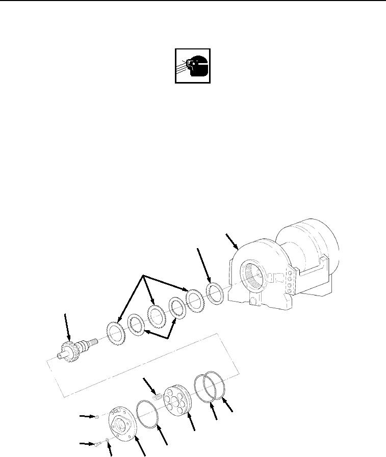
BRAKE HUB SUBASSEMBLY ASSEMBLY - Continued
WARNING
Wear safety goggles and use care when installing cover retainer. It is under spring tension
and can act as a projectile when released. Failure to comply may result in serious injury or
death to personnel.
6.
Install retaining ring (Figure 11, Item 20) and C-clip (Figure 11, Item 21) on machine-cut grooves in splined
end of motor drive shaft (Figure 11, Item 16).
END OF TASK
BRAKE HUB ASSEMBLY INSTALLATION
1.
Install brake hub subassembly (Figure 12, Item 11) in brake housing (Figure 12, Item 5), ensuring splined end
is in brake housing (Figure 12, Item 5) first. Rotate brake hub subassembly (Figure 12, Item 11) until it engages
with primary gear.
5
14
12
11
13
7
1
10
9
8
3
6
4
2
Figure 12. Brake Hub Assembly Installation.
2.
Install brake spacer (Figure 12, Item 14) in brake housing (Figure 12, Item 5), with recessed end down.
03/15/2011Rel(1.8)root(maintwp)wpno(M05030)