
TM 5-3990-263-13&P
0068
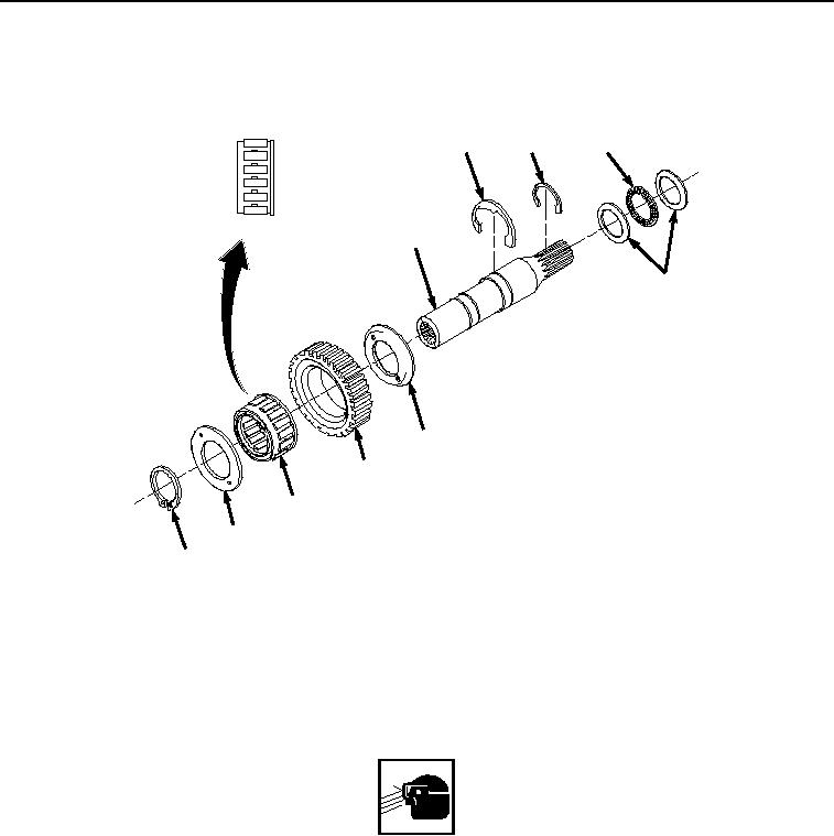
BRAKE HUB SUBASSEMBLY ASSEMBLY
1.
Install bearing (Figure 11, Item 19) in brake hub (Figure 11, Item 18), ensuring bearing (Figure 11, Item 19) lip
end goes into recessed side of brake hub (Figure 11, Item 18).
20
21
23
16
22
17
18
19
17
15
Figure 11.
Brake Hub Subassembly Assembly.
2.
Install two clutch liners (Figure 11, Item 17) on brake hub (Figure 11, Item 18), with recessed sides inward.
3.
Install raised side of brake hub (Figure 11, Item 18) on nonsplined end of motor drive shaft (Figure 11, Item
16), turning motor drive shaft (Figure 11, Item 16) counterclockwise until brake hub (Figure 11, Item 18) fits
securely on motor drive shaft (Figure 11, Item 16).
WARNING
Wear safety goggles and use caution when removing or installing springs, snaprings,
retaining rings, and other parts under spring tension. These parts are under tension and can
act as projectiles when released. Failure to comply may result in serious injury or death to
personnel.
4.
Install snapring (Figure 11, Item 15) on machine-cut groove in nonsplined end of motor drive shaft (Figure 11,
Item 16).
5.
Install two bearing seats (Figure 11, Item 22) and bearing (Figure 11, Item 23) on motor drive shaft (Figure 11,
Item 16).
03/15/2011Rel(1.8)root(maintwp)wpno(M05030)