
TM 5-3990-263-13&P
0067
ASSEMBLY - Continued
24
25
24
27
26
32
33
28
4
29
31
30
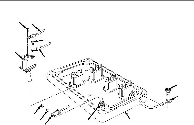
Figure 8.
Remote Control Unit Assembly.
13.
Install red wire (Figure 8, Item 30) on light (Figure 8, Item 31) with lockwasher (Figure 8, Item 29) and screw
(Figure 8, Item 28).
14.
Install red wire (Figure 8, Item 26) and yellow wire (Figure 8, Item 25) on HIGH IDLE switch (Figure 8, Item
27) with two screws (Figure 8, Item 24).
15.
Install spade connector (Figure 9, Item 22), spade connector (Figure 9, Item 21), and spade connector (Figure
9, Item 20) on WINCH switch (Figure 9, Item 23).
03/15/2011Rel(1.8)root(maintwp)wpno(M04101)