
TM 5-3990-263-13&P
0067
DISASSEMBLY - Continued
24
25
24
27
26
32
33
28
4
29
31
30
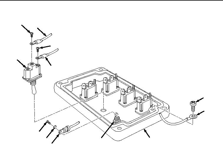
Figure 3. Remote Control Unit Disassembly.
10.
Remove screw (Figure 3, Item 28), lockwasher (Figure 3, Item 29), and red wire (Figure 3, Item 30) from light
(Figure 3, Item 31).
11.
Remove screw (Figure 3, Item 32) and brown wire (Figure 3, Item 33) from cover (Figure 3, Item 4).
NOTE
Note location and position of switches prior to disassembly to ensure proper assembly.
12.
Remove nut (Figure 4, Item 34), lockwasher (Figure 4, Item 35), and MAIN FRAME load/unload switch (Figure
4, Item 15) from cover (Figure 4, Item 4).
03/15/2011Rel(1.8)root(maintwp)wpno(M04101)