
TM 5-3990-263-13&P
0066
INSTALLATION - Continued
10
14
7
16
15
3
11
11
12
13
9
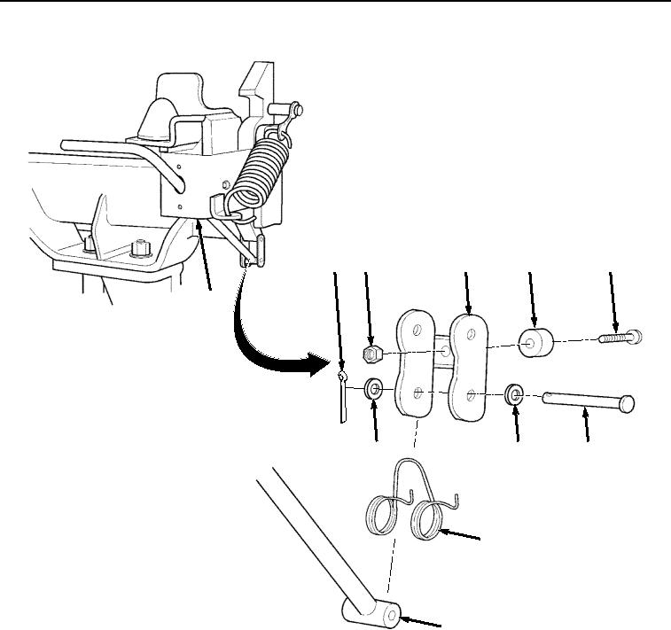
Figure 7. Front BAP Lock Handle Installation.
8.
Install bumper (Figure 7, Item 16) on bracket (Figure 7, Item 7) with screw (Figure 7, Item 15) and locknut
(Figure 7, Item 14).
NOTE
Handle faces rear of Transporter.
Ensure spring is installed in same position as noted prior to removal.
9.
Install handle (Figure 7, Item 9) and spring (Figure 7, Item 13) in bracket (Figure 7, Item 7) with pin (Figure 7,
Item 12), two washers (Figure 7, Item 11), and cotter pin (Figure 7, Item 10).
10.
Install handle (Figure 7, Item 9) in bracket (Figure 7, Item 3).
11.
Install bracket (Figure 8, Item 7) on lock (Figure 8, Item 8) with pin (Figure 8, Item 6), two washers (Figure 8,
Item 5), and cotter pin (Figure 8, Item 4).
03/15/2011Rel(1.8)root(maintwp)wpno(M04077)