
TM 5-3990-263-13&P
0067
DISASSEMBLY - Continued
42
44
31
43
41
40
4
46
45
11
34
35
27
36
37
38
39
15
19
23
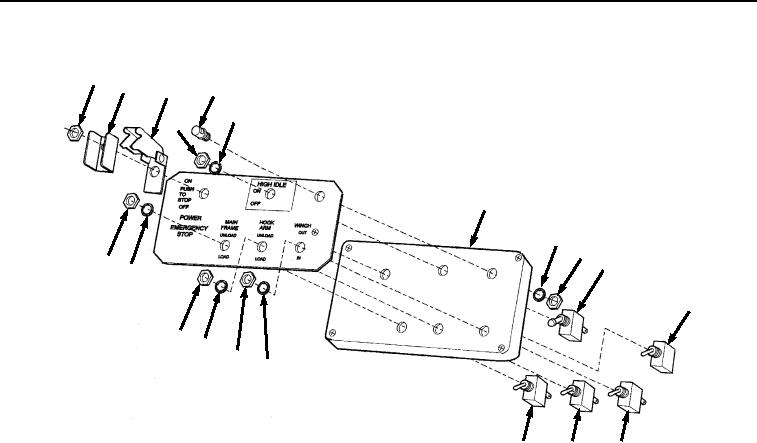
Figure 4. Remote Control Unit Disassembly.
13.
Remove nut (Figure 4, Item 36), lockwasher (Figure 4, Item 37), and HOOK ARM switch (Figure 4, Item 19)
from cover (Figure 4, Item 4).
14.
Remove nut (Figure 4, Item 38), lockwasher (Figure 4, Item 39), and WINCH switch (Figure 4, Item 23) from
cover (Figure 4, Item 4).
15.
Remove nut (Figure 4, Item 40), lockwasher (Figure 4, Item 41), and HIGH IDLE switch (Figure 4, Item 27)
from cover (Figure 4, Item 4).
16.
Remove nut (Figure 4, Item 42), snap cover (Figure 4, Item 43), switch guard (Figure 4, Item 44), and ON/OFF
switch (Figure 4, Item 11) from cover (Figure 4, Item 4).
17.
Remove nut (Figure 4, Item 45), lockwasher (Figure 4, Item 46), and light (Figure 4, Item 31) from cover (Figure
4, Item 4). Discard lockwasher.
18.
Remove connector (Figure 5, Item 47) from circuit board (Figure 5, Item 48).
03/15/2011Rel(1.8)root(maintwp)wpno(M04101)