
TM 5-3990-263-13&P
0056
DISASSEMBLY - Continued
NOTE
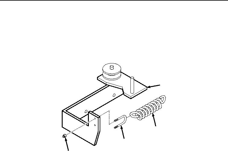
Note quantity of threads on u-bolt prior to removing locknuts to ensure proper tension on
spring during installation.
5.
Remove two locknuts (Figure 4, Item 16), u-bolt (Figure 4, Item 17), and spring (Figure 4, Item 11) from base
assembly (Figure 4, Item 4). Discard locknuts.
4
11
17
16
Figure 4.
Spring and U-bolt Removal.
END OF TASK
03/15/2011Rel(1.8)root(maintwp)wpno(M04112)