
TM 5-3990-263-13&P
0056
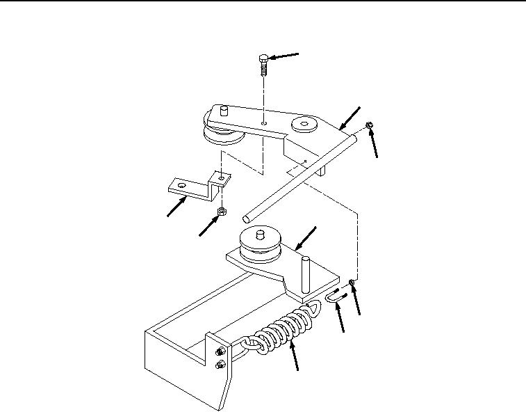
ASSEMBLY - Continued
13
3
9
4
15
14
12
10
11
Figure 6.
Handle Assembly Installation.
3.
Install handle assembly (Figure 6, Item 3) on base assembly (Figure 6, Item 4).
NOTE
Install jam-nuts and locknuts on u-bolt as noted prior to removal.
4.
Install two jam-nuts (Figure 6, Item 12) on u-bolt (Figure 6, Item 10).
5.
Install spring (Figure 6, Item 11) on handle assembly (Figure 6, Item 3) with u-bolt (Figure 6, Item 10) and two
locknuts (Figure 6, Item 9).
END OF TASK
INSTALLATION
1.
Install base assembly (Figure 7, Item 4) and handle assembly (Figure 7, Item 3) on winch frame (Figure 7,
Item 8) with two screws (Figure 7, Item 6) and locknuts (Figure 7, Item 7).
03/15/2011Rel(1.8)root(maintwp)wpno(M04112)