
TM 5-3990-263-13&P
0056
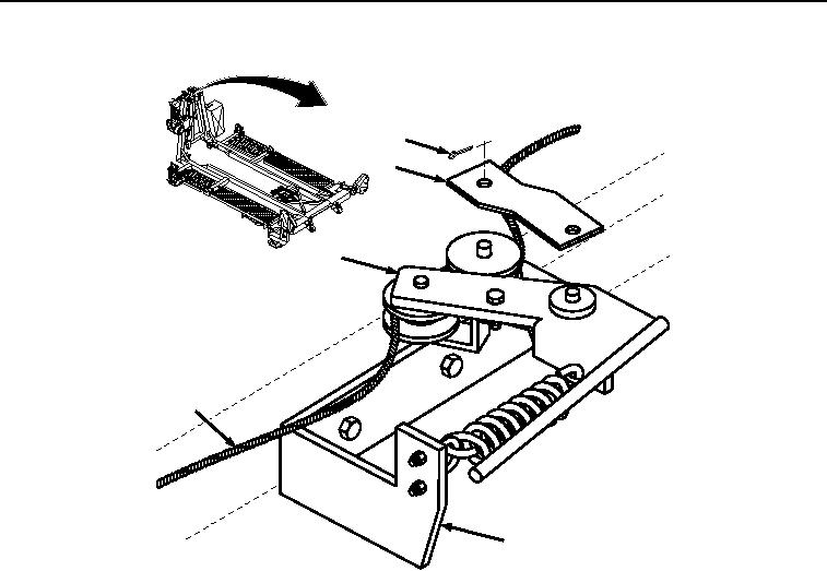
REMOVAL - Continued
1
2
3
5
4
Figure 1. Retainer Bar and Cable Assembly Removal.
2.
Remove cable assembly (Figure 1, Item 5) from handle assembly (Figure 1, Item 3) and base assembly (Figure
1, Item 4).
3.
Remove two screws (Figure 2, Item 6), locknuts (Figure 2, Item 7), handle assembly (Figure 2, Item 3), and
base assembly (Figure 2, Item 4) from winch frame (Figure 2, Item 8). Discard locknuts.
03/15/2011Rel(1.8)root(maintwp)wpno(M04112)