
TM 5-3990-263-13&P
0056
ASSEMBLY
NOTE
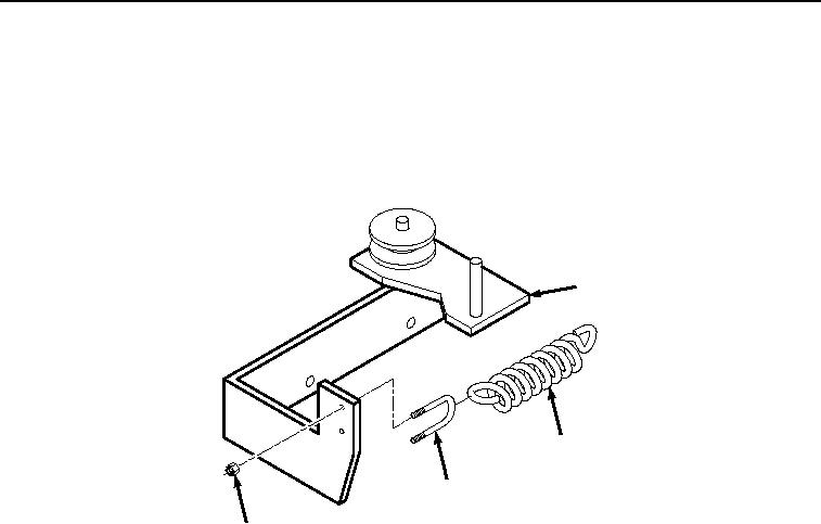
Install locknuts on u-bolt as noted prior to removal.
1.
Install spring (Figure 5, Item 11) on base assembly (Figure 5, Item 4) with u-bolt (Figure 5, Item 17) and two
locknuts (Figure 5, Item 16).
4
11
17
16
Figure 5. Spring and U-bolt Installation.
2.
Install torsion lock plate (Figure 6, Item 15) on handle assembly (Figure 6, Item 3) with screw (Figure 6, Item
13) and locknut (Figure 6, Item 14).
03/15/2011Rel(1.8)root(maintwp)wpno(M04112)