• Home
  • Download PDF
  • Order CD-ROM
  • Order in Print
Figure 6. Handle Assembly Installation
Figure 8. Retainer Bar and Cable Assembly Installation.

Parts Manual For Pallet, Adapter, Bridge M15 Page Navigation
  382    383    384    385    386  387  388    389    390    391    392  
img
.
TM 5-3990-263-13&P
0056
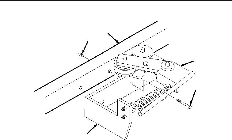
INSTALLATION - Continued
8
7
3
6
4
Figure 7. Base Assembly Installation.
2.
Install cable assembly (Figure 8, Item 5) on handle assembly (Figure 8, Item 3) and base assembly (Figure 8,
Item 4).
0056-8
03/15/2011Rel(1.8)root(maintwp)wpno(M04112)


Privacy Statement
Press Release
Contact

© Copyright Integrated Publishing, Inc.. All Rights Reserved.