
TM 5-3990-263-13&P
0057
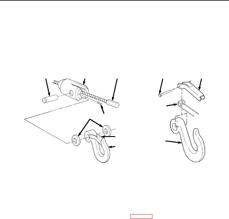
DISASSEMBLY - Continued
3.
Remove hook latch kit (Figure 3, Item 7) by driving out rivet (Figure 3, Item 8) and removing latch (Figure 3,
Item 9) and spring (Figure 3, Item 10) from hook (Figure 3, Item 4). Discard hook latch kit.
END OF TASK
ASSEMBLY
1.
Install latch (Figure 4, Item 9), spring (Figure 4, Item 10), and rivet (Figure 4, Item 8) on hook (Figure 4, Item
4).
3
2
6
8
9
10
5
1
7
4
4
Figure 4. Cable Assembly.
2.
Slide hook holder (Figure 4, Item 2) over cable (Figure 4, Item 6) until cable (Figure 4, Item 6) is fully seated
in hook holder (Figure 4, Item 2).
3.
Install two spacers (Figure 4, Item 5), hook (Figure 4, Item 4), and pin (Figure 4, Item 3) in hook holder (Figure
4, Item 2). Ensure pin (Figure 4, Item 3) is installed with groove under setscrew (Figure 4, Item 1).
4.
Install setscrew (Figure 4, Item 1) in hook holder (Figure 4, Item 2).
5.
Lubricate cable in accordance with Lubrication Instructions (WP 0070).
END OF TASK
INSTALLATION
1.
Install cable (Figure 5, Item 5) on winch frame (Figure 5, Item 8) and through pulley (Figure 5, Item 11), cable
tensioner (Figure 5, Item 10), and roller (Figure 5, Item 9) and on winch (Figure 5, Item 7).
03/15/2011Rel(1.8)root(maintwp)wpno(M04050)