
TM 5-3990-263-13&P
0058
REMOVAL - Continued
2.
Remove two hydraulic tubes (Figure 1, Item 3) from two elbows (Figure 1, Item 4). Loosen two captive nuts
(Figure 1, Item 5), then remove two elbows (Figure 1, Item 4) and preformed packings (Figure 1, Item 6) from
winch motor (Figure 1, Item 7). Remove tube (Figure 1, Item 8) from elbow (Figure 1, Item 9). Discard preformed
packings.
3.
Remove pipe plug (Figure 1, Item 10) from end cover (Figure 1, Item 11), and drain oil into a suitable container.
Install pipe plug (Figure 1, Item 10) in end cover (Figure 1, Item 11).
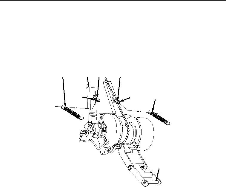
4.
Remove two cable guide springs (Figure 2, Item 12) from two bolts (Figure 2, Item 13) and brackets (Figure
2, Item 14) on winch frame (Figure 2, Item 15) and upper cable guide shaft (Figure 2, Item 16).
12
15
14
14
13
13
12
16
Figure 2. Upper Cable guide Shaft Removal.
5.
Remove two cotter pins (Figure 3, Item 17) and upper cable guide shaft (Figure 3, Item 16) from two upper
cable guide retainers (Figure 3, Item 18). Remove two cotter pins (Figure 3, Item 19) and lower cable guide
shaft (Figure 3, Item 20) from carriage (Figure 3, Item 21) and two pivot plates (Figure 3, Item 22). Discard
cotter pins.
03/15/2011Rel(1.8)root(maintwp)wpno(M04051)