TM 5-3990-263-13&P
0058
REMOVAL - Continued
19
20
22
22
19
21
26
24
25
17
18
23
16
26
18
17
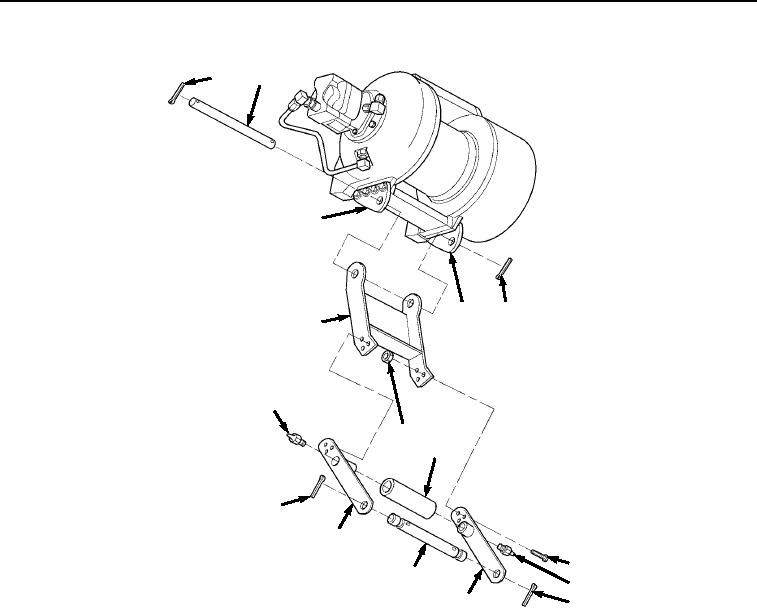
Figure 3.
Lower Cable Guide Shaft Removal.
6.
Remove six screws (Figure 3, Item 23), nuts (Figure 3, Item 24), two upper cable guide retainers (Figure 3,
Item 18), and roller assembly (Figure 3, Item 25) from carriage (Figure 3, Item 21). Remove two grease fittings
(Figure 3, Item 26) from roller assembly (Figure 3, Item 25).
NOTE
When replacing an old winch assembly with a new winch assembly, remove eight bolts
from new winch assembly and exchange with those on winch being turned in for repair.
Bolts used to mount pivot plates are longer than those shipped with new winch assembly.
Be sure to ship old winch with all shorter bolts.
Replace the two pivot plates one at a time.
7.
Remove four bolts (Figure 4, Item 27) and lockwashers (Figure 4, Item 28) from each of two pivot plates (Figure
4, Item 22). Remove two pivot plates (Figure 4, Item 22) from winch assembly (Figure 4, Item 29). Discard
lockwashers. Temporarily reinstall four bolts (Figure 4, Item 27) in winch assembly (Figure 4, Item 29).
03/15/2011Rel(1.8)root(maintwp)wpno(M04051)

