
TM 5-3990-263-13&P
0056
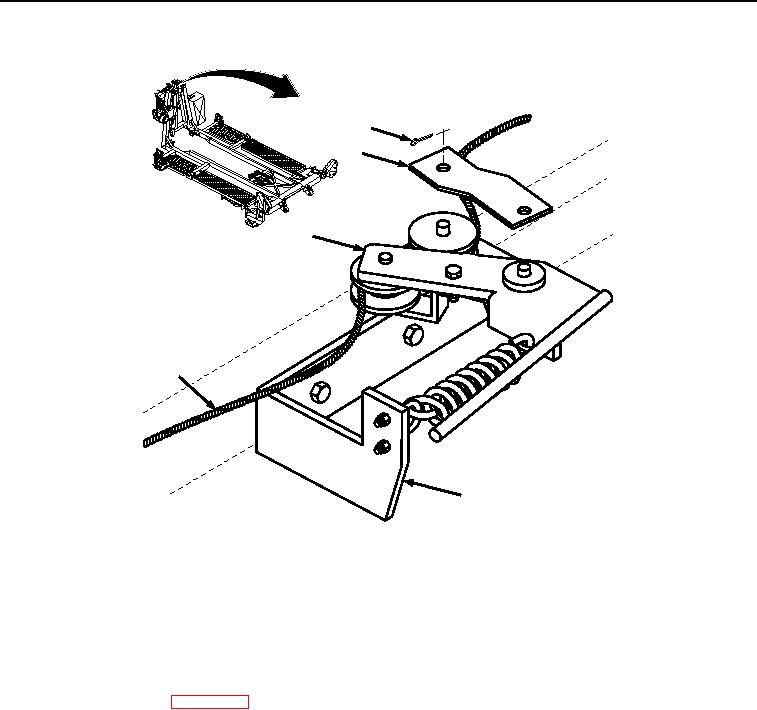
INSTALLATION - Continued
1
2
3
5
4
Figure 8. Retainer Bar and Cable Assembly Installation.
3.
Install retainer bar (Figure 8, Item 2) on handle assembly (Figure 8, Item 3) and base assembly (Figure 8, Item
4) with two cotter pins (Figure 8, Item 1).
END OF TASK
FOLLOW-ON MAINTENANCE
1.
Reel in winch cable. (WP 0008)
2.
Remove wheel chocks. (TM 9-2320-435-10 or TM 9-2320-425-10).
END OF TASK
END OF WORK PACKAGE