
TM 5-3990-263-13&P
0055
INSTALLATION - Continued
35
33
34
36
28
24
25
26
31
27
32
23
30
22
29
18
17
20
14
19
16
15
14
21
15
18
12
10
13
11
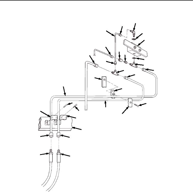
Figure 7. Winch Hydraulic Tube Bracket Installation.
11.
Install tube nut (Figure 7, Item 33) and tube (Figure 7, Item 34) on elbow (Figure 7, Item 35). Install tee (Figure
7, Item 30) on tube nut (Figure 7, Item 32) and tube (Figure 7, Item 34). Install tube nut (Figure 7, Item 31) on
tee (Figure 7, Item 30).
12.
Install reducer (Figure 7, Item 26) and tube nut (Figure 7, Item 25) on tee (Figure 7, Item 23).
13.
Install tube nut (Figure 7, Item 24) on tube nut (Figure 7, Item 25). Install tube nut (Figure 7, Item 22) and tube
(Figure 7, Item 17) on tee (Figure 7, Item 23). Install tube nut (Figure 7, Item 29) and tube (Figure 7, Item 16)
on tee (Figure 7, Item 30).
14.
Install screw (Figure 7, Item 19), clamp block (Figure 7, Item 20), and arched cover plate (Figure 7, Item 21)
on two tubes (Figure 7, Items 16 and 17) and winch frame (Figure 7, Item 18).
03/15/2011Rel(1.8)root(maintwp)wpno(M04049)