
TM 5-3990-263-13&P
0059
REMOVAL - Continued
1
2
1
3
10
5
7
11
18
13 15 16
9
8
6
12
2
4
14
17
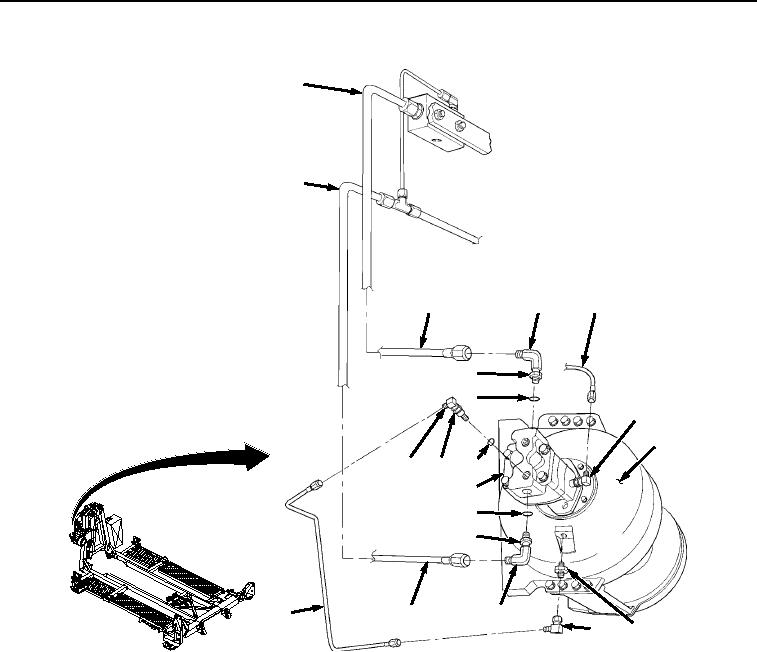
Figure 1. Winch Motor Tubes Removal.
2.
Remove tube (Figure 1, Item 10) from elbow (Figure 1, Item 11).
3.
Remove tube (Figure 1, Item 12) from elbow (Figure 1, Item 13) on motor (Figure 1, Item 9). Remove other
end of tube (Figure 1, Item 12) from elbow (Figure 1, Item 14).
4.
Loosen captive nut (Figure 1, Item 15) and remove elbow (Figure 1, Item 13) and O-ring (Figure 1, Item 16)
from motor (Figure 1, Item 9). Remove elbow (Figure 1, Item 14) and adapter (Figure 1, Item 17) from winch
housing (Figure 1, Item 18). Discard O-ring.
5.
Remove two bolts (Figure 2, Item 19), lockwashers (Figure 2, Item 20), and winch hydraulic motor (Figure 2,
Item 9) from winch housing (Figure 2, Item 18). Remove O-ring (Figure 2, Item 21) from base of winch hydraulic
motor (Figure 2, Item 9). Discard lockwashers and O-ring.
03/15/2011Rel(1.8)root(maintwp)wpno(M04052)