
TM 5-3990-263-13&P
0059
REMOVAL - Continued
9
23
22
11
18
21
19
20
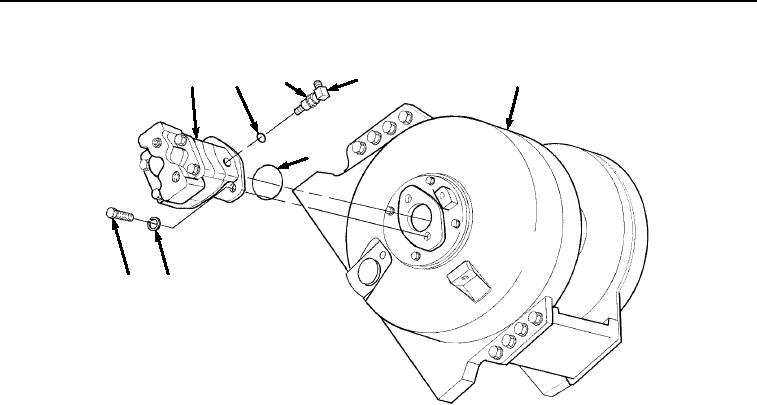
Figure 2.
Winch Motor Assembly Removal.
6.
Loosen captive nut (Figure 2, Item 22) and remove elbow (Figure 2, Item 11) and O-ring (Figure 2, Item 23)
from winch hydraulic motor (Figure 2, Item 9). Discard O-ring.
END OF TASK
INSTALLATION
1.
Coat O-ring (Figure 3, Item 21) with grease and install on base of winch hydraulic motor (Figure 3, Item 9).
Install elbow (Figure 3, Item 11) and O-ring (Figure 3, Item 23) to align with the end of tube (Figure 4, Item 10)
when winch hydraulic motor (Figure 3, Item 9) is installed on winch housing (Figure 3, Item 18).
03/15/2011Rel(1.8)root(maintwp)wpno(M04052)