
TM 5-3990-263-13&P
0060
REMOVAL - Continued
3
2
1
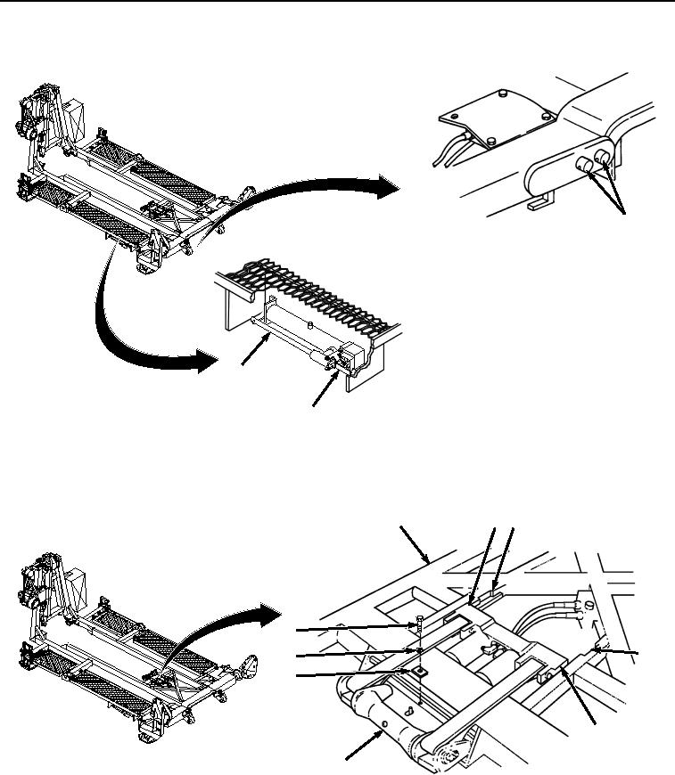
Figure 1. Center Roller Hydraulic System Pressure Relief.
2.
Remove screw (Figure 2, Item 4), lockwasher (Figure 2, Item 5), and retainer (Figure 2, Item 6) from BAP frame
(Figure 2, Item 7). Discard lockwasher.
9 10
7
4
10
5
6
9
8
Figure 2.
Center Roller Hydraulic System Removal.
3.
Lift and move center roller assembly (Figure 2, Item 8) toward rear of the BAP until tabs on rear carriage (Figure
2, Item 9) align with two notches in track (Figure 2, Item 10) of BAP frame (Figure 2, Item 7), then lift center
roller assembly (Figure 2, Item 8) clear of BAP frame (Figure 2, Item 7).
03/15/2011Rel(1.8)root(maintwp)wpno(M04053)