
TM 5-3990-263-13&P
0060
INSTALLATION - Continued
17
14
9
16
13
11
12
15
13
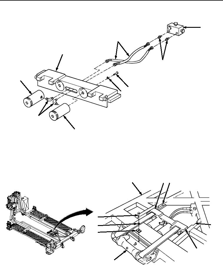
Figure 6. Rear Carriage Installation.
8.
Install two fittings (Figure 6, Item 16) on manifold (Figure 6, Item 17). Install two hydraulic hoses (Figure 6,
Item 14) and elbows (Figure 6, Item 15) on two hydraulic cylinders (Figure 6, Item 13).
9.
Align track (Figure 7, Item 10) in BAP frame (Figure 7, Item 7) with tabs on rear carriage (Figure 7, Item 9),
and install center roller assembly (Figure 7, Item 8) on frame (Figure 7, Item 7).
9 10
7
4
10
5
6
9
8
Figure 7. Center Roller Hydraulic System Installation.
03/15/2011Rel(1.8)root(maintwp)wpno(M04053)