
TM 5-3990-263-13&P
0060
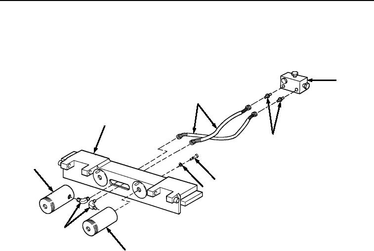
REMOVAL - Continued
4.
Remove two screws (Figure 3, Item 11) and lockwashers (Figure 3, Item 12) from rear carriage (Figure 3, Item
9) and two BAP center roller hydraulic cylinders (Figure 3, Item 13). Remove hydraulic cylinders (Figure 3,
Item 13) from rear carriage (Figure 3, Item 9). Discard lockwashers.
17
14
9
16
13
11
12
15
13
Figure 3.
Rear Carriage Removal.
5.
Remove two hydraulic hoses (Figure 3, Item 14) and elbows (Figure 3, Item 15) from two hydraulic cylinders
(Figure 3, Item 13). Remove two fittings (Figure 3, Item 16) from manifold (Figure 3, Item 17) and hydraulic
hoses (Figure 3, Item 14).
6.
Remove tube (Figure 4, Item 18) from fitting (Figure 4, Item 19). Remove fitting (Figure 4, Item 19) from manifold
(Figure 4, Item 17).
03/15/2011Rel(1.8)root(maintwp)wpno(M04053)