
TM 5-3990-263-13&P
0059
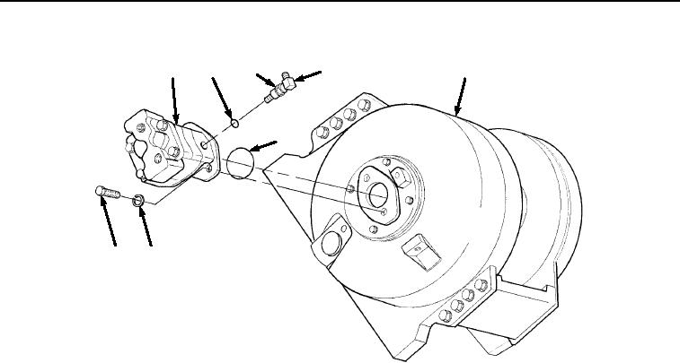
INSTALLATION - Continued
9
23
22
11
18
21
19
20
Figure 3. Winch Motor Assembly Installation.
CAUTION
Be careful not to damage O-ring by pinching it between the winch motor base and the winch
housing when installing winch motor. Failure to comply may result in damage to equipment.
2.
Carefully position winch hydraulic motor (Figure 3, Item 9) on winch housing (Figure 3, Item 18), and install
two bolts (Figure 3, Item 19) and lockwashers (Figure 3, Item 20) on winch housing (Figure 3, Item 18).
3.
Install adapter (Figure 4, Item 17) on winch housing (Figure 4, Item 18). Install elbow (Figure 4, Item 14) on
adapter (Figure 4, Item 17), but do not tighten. Install tube (Figure 4, Item 12) on elbow (Figure 4, Item 14).
03/15/2011Rel(1.8)root(maintwp)wpno(M04052)