
TM 5-3990-263-13&P
0059
INSTALLATION - Continued
1
2
1
3
10
5
7
11
18
13 15 16
9
8
6
12
2
4
14
17
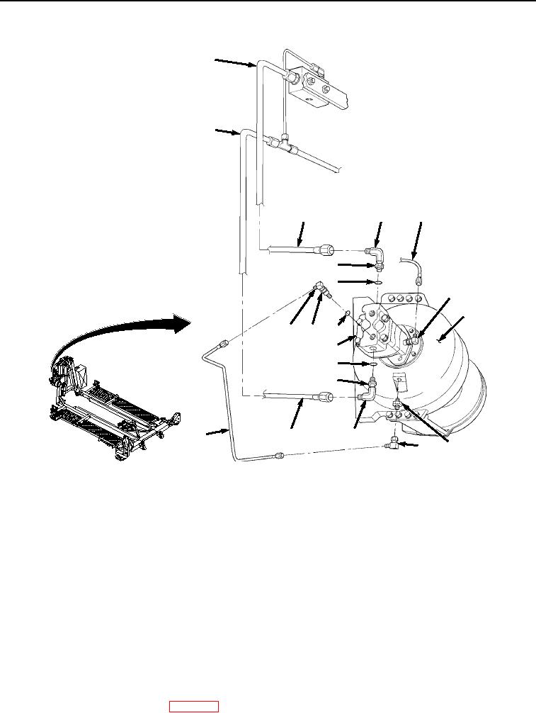
Figure 4.
Winch Motor Tubes Installation.
4.
Install elbow (Figure 4, Item 13) and O-ring (Figure 4, Item 16) on winch hydraulic motor (Figure 4, Item 9) to
align with tube (Figure 4, Item 12). Install tube (Figure 4, Item 12) on elbow (Figure 4, Item 13). Tighten captive
nut (Figure 4, Item 15) on motor (Figure 4, Item 9). Install elbow (Figure 4, Item 14) on adapter (Figure 4, Item
17).
5.
Install tube (Figure 4, Item 10) on elbow (Figure 4, Item 11), then tighten captive nut (Figure 3, Item 22) on
motor (Figure 4, Item 9).
6.
Install two elbows (Figure 4, Items 3 and 4) and O-rings (Figure 4, Items 7 and 8) on winch hydraulic motor
(Figure 4, Item 9), then tighten two captive nuts (Figure 4, Items 5 and 6) on winch hydraulic motor (Figure 4,
Item 9).
7.
Tighten both ends of two tubes (Figure 4, Items 1 and 2) on two elbows (Figure 4, Items 3 and 4).
END OF TASK
FOLLOW-ON MAINTENANCE
1.
Load the BAP on the vehicle. (WP 0005)
03/15/2011Rel(1.8)root(maintwp)wpno(M04052)