
TM 5-3990-263-13&P
0060
REMOVAL - Continued
20
21
23
22
24
29
19
17
7
25
18
26
27
33
30
32
37
31
28
35
7
34
36
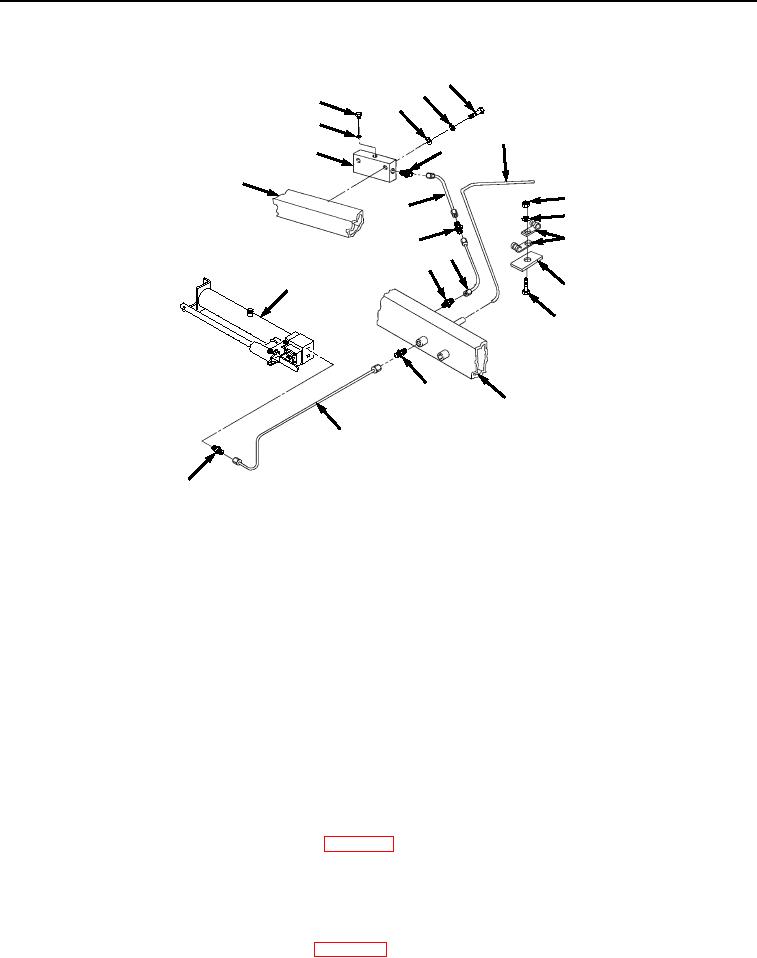
Figure 4. Manifold Removal.
7.
Remove two bolts (Figure 4, Item 20), lockwashers (Figure 4, Item 21), washers (Figure 4, Item 22) and
manifold (Figure 4, Item 17) from frame (Figure 4, Item 7). Remove plug (Figure 4, Item 23) and O-ring (Figure
4, Item 24) from manifold (Figure 4, Item 17). Discard lockwashers and O-ring.
8.
Remove two nuts (Figure 4, Item 25), lockwashers (Figure 4, Item 26), four cushion clamps (Figure 4, Item
27), and two bolts (Figure 4, Item 28) from tubes (Figure 4, Items 29 and 30) and welded bracket (Figure 4,
Item 31) on frame (Figure 4, Item 7). Discard lockwashers.
9.
Remove tube (Figure 4, Item 30) from two fittings (Figure 4, Items 32 and 33). Remove fitting (Figure 4, Item
32) from frame (Figure 4, Item 7). Remove fitting (Figure 4, Item 33) from tube (Figure 4, Item 18).
10.
Remove tube (Figure 4, Item 34) from two fittings (Figure 4, Items 35 and 36). Remove fitting (Figure 4, Item
35) from frame (Figure 4, Item 7). Remove fitting (Figure 4, Item 36) from hand pump (Figure 4, Item 37).
END OF TASK
CLEANING
Refer to General Maintenance Instructions (WP 0038) for general cleaning instructions.
END OF TASK
INSPECTION
1.
Refer to General Maintenance Instructions (WP 0038) for general inspection instructions.
03/15/2011Rel(1.8)root(maintwp)wpno(M04053)