TM 5-3990-263-13&P
0061
REMOVAL - Continued
8.
Remove tube (Figure 3, Item 30) from tee (Figure 3, Item 26) and fitting (Figure 3, Item 31). Remove fitting
(Figure 3, Item 31) from frame (Figure 3, Item 18).
9.
Remove two screws (Figure 3, Item 32), lockwashers (Figure 3, Item 33), and washers (Figure 3, Item 34) and
manifold (Figure 3, Item 13) from frame (Figure 3, Item 18). Remove plug (Figure 3, Item 35) and O-ring (Figure
3, Item 36) from manifold (Figure 3, Item 13). Discard lockwashers and O-ring.
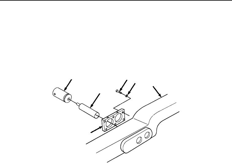
10.
Unscrew and remove two hydraulic cylinders (Figure 4, Item 11) and extensions (Figure 4, Item 37) from
mounting plate (Figure 4, Item 7). Remove extension cylinders (Figure 4, Item 37) from hydraulic cylinders
(Figure 4, Item 11).
11
38
39
18
37
7
Figure 4. Transload Roller Hydraulic Cylinder Removal.
11.
Remove six screws (Figure 4, Item 38), lockwashers (Figure 4, Item 39), and mounting plate (Figure 4, Item
7) from frame (Figure 4, Item 18). Discard lockwashers.
NOTE
Steps (12) through (14) are for curb-side hydraulics only.
12.
Remove two screws (Figure 5, Item 40), nuts (Figure 5, Item 41), lockwashers (Figure 5, Item 42), and four
cushion clamps (Figure 5, Item 43) from tube (Figure 5, Item 44) and frame bracket (Figure 5, Item 45). Discard
lockwashers.
03/15/2011Rel(1.8)root(maintwp)wpno(M04054)

