
TM 5-3990-263-13&P
0061
INSTALLATION - Continued
14
16
15
19
18
20
23
18
22
21
17
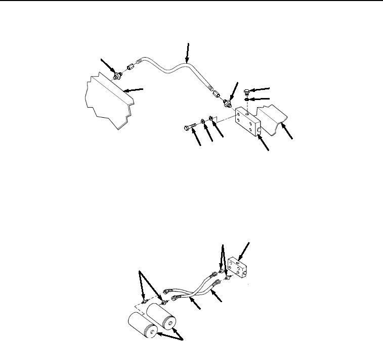
Figure 9.
Transload Roller Hydraulic System Hose Installation.
13.
Install fitting (Figure 9, Item 16) on frame (Figure 9, Item 18). Install fitting (Figure 9, Item 15) on manifold
(Figure 9, Item 17). Install hose (Figure 9, Item 14) on two fittings (Figure 9, Items 15 and 16).
14.
Install two fittings (Figure 10, Item 12) on manifold (Figure 10, Item 13). Install two hoses (Figure 10, Items 8
and 9) on fittings (Figure 10, Item 12).
13
12
10
9
8
11
Figure 10.
Transload Roller Hydraulic System Fittings Installation.
15.
Install two fittings (Figure 10, Item 10) on two hydraulic cylinders (Figure 10, Item 11).
16.
Install other end of each hose (Figure 10, Items 8 and 9) on two fittings (Figure 10, Item 10).
17.
Install two screws (Figure 11, Item 5), lockwashers (Figure 11, Item 6), and guard plate (Figure 11, Item 4) on
mounting plate (Figure 11, Item 7) and frame (Figure 11, Item 18). Install screw (Figure 11, Item 1), lockwasher
(Figure 11, Item 2), and nut (Figure 11, Item 3) on mounting plate (Figure 11, Item 7).
03/15/2011Rel(1.8)root(maintwp)wpno(M04054)