
TM 5-3990-263-13&P
0061
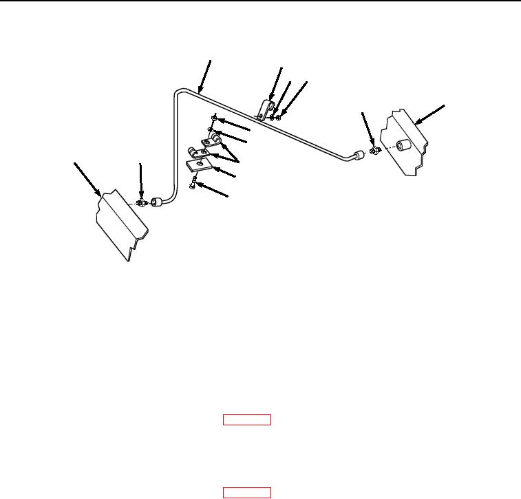
REMOVAL - Continued
44
48
47 46
18
49
41
42
18
49
43
45
40
Figure 5. Transload Roller Hydraulic System Cushion Clamps Removal.
13.
Remove nut (Figure 5, Item 46), lockwasher (Figure 5, Item 47), and clamp (Figure 5, Item 48) from tube (Figure
5, Item 44) and frame (Figure 5, Item 18). Discard lockwasher.
14.
Remove tube (Figure 5, Item 44) from two fittings (Figure 5, Item 49). Remove two fittings (Figure 5, Item 49)
from frame (Figure 5, Item 18).
END OF TASK
CLEANING
Refer to General Maintenance Instructions (WP 0038) for general cleaning instructions.
END OF TASK
INSPECTION
Refer to General Maintenance Instructions (WP 0038) for general inspection instructions.
END OF TASK
INSTALLATION
NOTE
Steps (1) through (6) are for curb side only. Perform Step (7) for road-side hydraulics.
Apply Antiseizing tape to all fittings that fit into cylinders or manifolds.
1.
Install two fittings (Figure 6, Item 49) on frame (Figure 6, Item 18).
03/15/2011Rel(1.8)root(maintwp)wpno(M04054)