TM 5-3990-263-13&P
0061
INSTALLATION - Continued
44
48
47 46
18
49
41
42
18
49
43
45
40
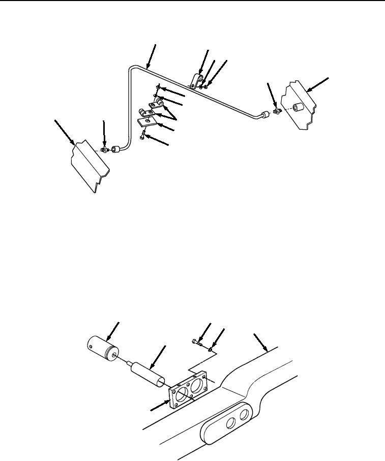
Figure 6. Transload Roller Hydraulic System Cushion Clamps Installation.
2.
Install tube (Figure 6, Item 44) on two fittings (Figure 6, Item 49).
3.
Install nut (Figure 6, Item 46), lockwasher (Figure 6, Item 47), and clamp (Figure 6, Item 48) on tube (Figure
6, Item 44) and frame (Figure 6, Item 18).
4.
Install two screws (Figure 6, Item 40), nuts (Figure 6, Item 41), lockwashers (Figure 6, Item 42), and four
cushion clamps (Figure 6, Item 43) on tube (Figure 6, Item 44) and frame bracket (Figure 6, Item 45).
5.
Install six screws (Figure 7, Item 38), lockwashers (Figure 7, Item 39), and mounting plate (Figure 7, Item 7)
on frame (Figure 7, Item 18). Make sure mounting plate (Figure 7, Item 7) is installed with two small holes on
top.
11
38
39
18
37
7
Figure 7.
Transload Roller Hydraulic System Cylinder Installation.
6.
Install two extensions (Figure 7, Item 37) on two hydraulic cylinders (Figure 7, Item 11).
7.
Install two hydraulic cylinders (Figure 7, Item 11) on mounting plate (Figure 7, Item 7).
03/15/2011Rel(1.8)root(maintwp)wpno(M04054)

