
TM 5-3990-263-13&P
0062
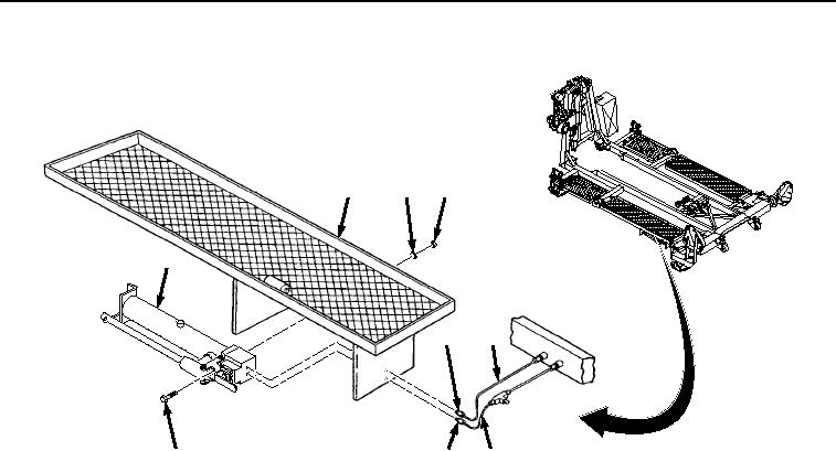
REMOVAL - Continued
9
8
7
5
3
1
6
4
2
Figure 1. Hydraulic Hand Pump Removal.
2.
Remove four screws (Figure 1, Item 6), nuts (Figure 1, Item 7), and lockwashers (Figure 1, Item 8) from hand
pump (Figure 1, Item 5). Discard lockwashers.
3.
Remove hand pump (Figure 1, Item 5) from catwalk (Figure 1, Item 9).
END OF TASK
INSTALLATION
1.
Install hand pump (Figure 2, Item 5) and four screws (Figure 2, Item 6), nuts (Figure 2, Item 7), and lockwashers
(Figure 2, Item 8) on catwalk (Figure 2, Item 9).
03/15/2011Rel(1.8)root(maintwp)wpno(M04056)