
TM 5-3990-263-13&P
0063
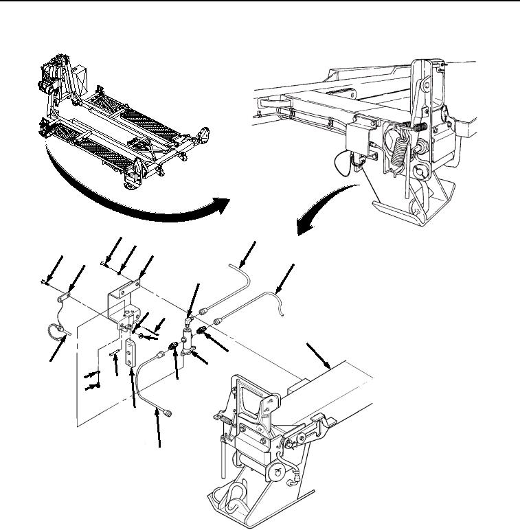
REMOVAL - Continued
8
17
9
10
2
12
19
16
11
4
15
13
18
1
14
7
5
18
6
3
19
Figure 1. Control Valve Removal.
2.
Remove cotter pin (Figure 1, Item 4), straight pin (Figure 1, Item 5), and lever (Figure 1, Item 3) from valve
bracket (Figure 1, Item 2). Discard cotter pin.
3.
Remove two screws (Figure 1, Item 6) and lockwashers (Figure 1, Item 7) from valve bracket (Figure 1, Item
2). Discard lockwashers.
4.
Remove two bolts (Figure 1, Item 8) and lockwashers (Figure 1, Item 9) from valve bracket (Figure 1, Item 2).
Discard lockwashers.
03/15/2011Rel(1.8)root(maintwp)wpno(M04057)