• Home
  • Download PDF
  • Order CD-ROM
  • Order in Print
Figure 1. Hydraulic Hand Pump Removal.
Figure 3. Hydraulic Hand Pump Bleeding

Parts Manual For Pallet, Adapter, Bridge M15 Page Navigation
  425    426    427    428    429  430  431    432    433    434    435  
img
.
TM 5-3990-263-13&P
0062
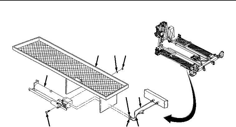
INSTALLATION - Continued
9
8
7
5
3
1
6
4
2
Figure 2. Hydraulic Hand Pump Installation.
2.
Install two hydraulic tubes (Figure 2, Items 1 and 2) and fittings (Figure 2, Items 3 and 4) to hand pump (Figure
2, Item 5).
END OF TASK
BLEEDING
1.
Remove dipstick (Figure 3, Item 1) from hand pump (Figure 3, Item 2).
0062-3
03/15/2011Rel(1.8)root(maintwp)wpno(M04056)


Privacy Statement
Press Release
Contact

© Copyright Integrated Publishing, Inc.. All Rights Reserved.