
TM 5-3990-263-13&P
0063
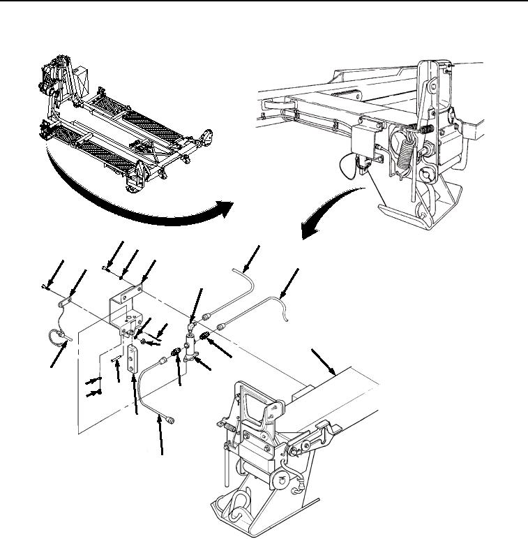
INSTALLATION - Continued
8
17
9
10
2
12
19
16
11
4
15
13
18
1
14
7
5
18
6
3
19
Figure 2.
Control Valve Installation.
2.
Install two adapters (Figure 2, Item 18) on two tubings (Figure 2, Item 19).
3.
Install elbow (Figure 2, Item 16) on tubing (Figure 2, Item 17).
4.
Install valve bracket (Figure 2, Item 2) and lanyard (Figure 2, Item 12) on control valve (Figure 2, Item 14) and
frame (Figure 2, Item 15) with two nuts (Figure 2, Item 13), two bolts (Figure 2, Item 10), and lockwashers
(Figure 2, Item 11).
5.
Install two bolts (Figure 2, Item 8) and lockwashers (Figure 2, Item 9) on valve bracket (Figure 2, Item 2).
6.
Install two screws (Figure 2, Item 6) and lockwashers (Figure 2, Item 7) on valve bracket (Figure 2, Item 2).
03/15/2011Rel(1.8)root(maintwp)wpno(M04057)