
TM 5-3990-263-13&P
0064
REMOVAL - Continued
1
5
3
2
7
4
6
9
8
12
30
10
33
31
35
11
32
14
27 24
15
16
25
18
36
10
37
13
17
31
28
34
22 17
19
21
29
23
26
20
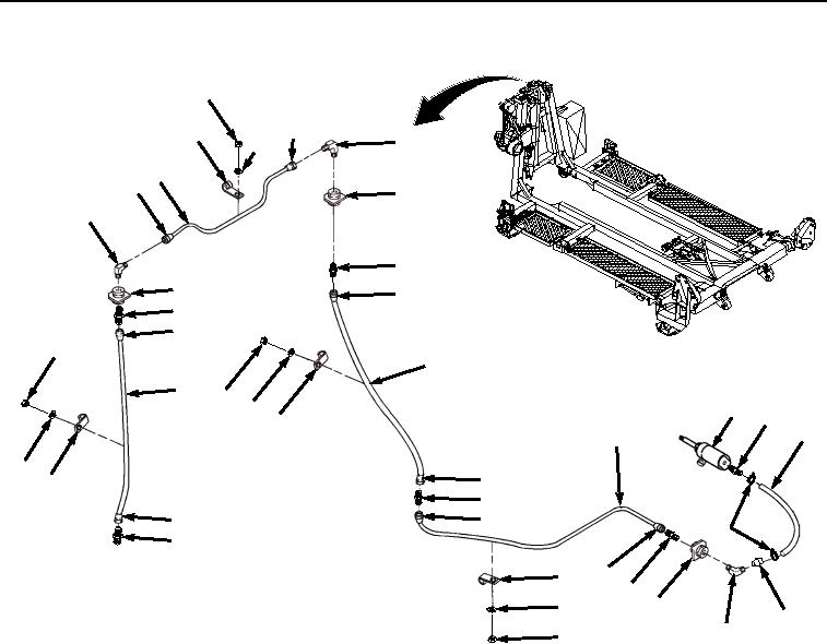
Figure 1. Tubing Removal.
2.
Loosen tube nuts (Figure 1, Items 5 and 6) on each end of tubing (Figure 1, Item 4), and disconnect tubing
(Figure 1, Item 4) from two elbows (Figure 1, Items 7 and 8).
NOTE
Steps (3) through (11) apply to curb-side air lines. Proceed to Step (12) for road-side air lines.
3.
Remove elbow (Figure 1, Item 7) from pipe coupling (Figure 1, Item 9).
4.
Loosen tube nuts (Figure 1, Item 10) on each end of tubing (Figure 1, Item 11), and disconnect tubing (Figure
1, Item 11) from adapter (Figure 1, Item 12) and tube nipple (Figure 1, Item 13). Remove adapter (Figure 1,
Item 12) from pipe coupling (Figure 1, Item 9).
5.
Remove six nuts (Figure 1, Item 14), lockwashers (Figure 1, Item 15), and loop clamps (Figure 1, Item 16)
from tubing (Figure 1, Item 11). Remove tubing (Figure 1, Item 11) from BAP frame. Discard lockwashers.
6.
Remove adapter (Figure 1, Item 12) and pipe coupling (Figure 1, Item 9) from BAP frame.
7.
Loosen tube nuts (Figure 1, Item 17) on each end of tubing (Figure 1, Item 18), and disconnect tubing (Figure
1, Item 18) from tube nipple (Figure 1, Item 13) and adapter (Figure 1, Item 19).
8.
Remove six nuts (Figure 1, Item 20), lockwashers (Figure 1, Item 21), and loop clamps (Figure 1, Item 22)
from tubing (Figure 1, Item 18). Remove tubing (Figure 1, Item 18) from BAP frame. Discard lockwashers.
03/15/2011Rel(1.8)root(maintwp)wpno(M04058)