
TM 5-3990-263-13&P
0061
REMOVAL - Continued
14
16
15
19
18
20
23
18
22
21
17
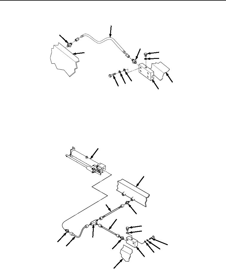
Figure 2. Transload Roller Hydraulic System Hose Removal.
5.
Remove plug (Figure 2, Item 19) and O-ring (Figure 2, Item 20) from manifold (Figure 2, Item 17). Remove
two screws (Figure 2, Item 21), lockwashers (Figure 2, Item 22), and washers (Figure 2, Item 23) and manifold
(Figure 2, Item 17) from frame (Figure 2, Item 18). Discard O-ring and lockwashers.
6.
Remove tube (Figure 3, Item 24) from fitting (Figure 3, Item 25) and tee (Figure 3, Item 26). Remove fitting
(Figure 3, Item 25) from manifold (Figure 3, Item 13).
29
18
30
24
31
35
36
26
28
32
27
33
25
34
13
18
Figure 3.
Transload Roller Hydraulic System Tube Removal.
7.
Remove tube (Figure 3, Item 27) from tee (Figure 3, Item 26) and fitting (Figure 3, Item 28). Remove fitting
(Figure 3, Item 28) from hand pump (Figure 3, Item 29).
03/15/2011Rel(1.8)root(maintwp)wpno(M04054)