
TM 5-3990-263-13&P
0052
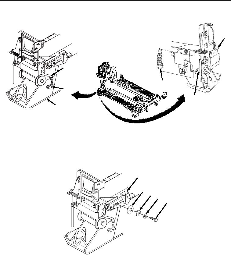
REMOVAL - Continued
6
1
4
2
5
3
Figure 1.
Air Hose Removal.
2.
Disengage extension spring (Figure 1, Item 4) from pin lock bracket (Figure 1, Item 5) and front pin lock guide
(Figure 1, Item 6).
3.
Remove bolt (Figure 2, Item 7), lockwasher (Figure 2, Item 8), and two washers (Figure 2, Items 9 and 10)
from pivot latch (Figure 2, Item 11). Discard lockwasher.
11
10
9
8
7
Figure 2. BAP Front Pin Lock Assembly Removal.
END OF TASK
DISASSEMBLY
1.
Remove two bolts (Figure 3, Item 12), lockwashers (Figure 3, Item 13), and air cylinder guard (Figure 3, Item
14) from pin lock guide (Figure 3, Item 6). Discard lockwashers.
03/15/2011Rel(1.8)root(maintwp)wpno(M04047)