
TM 5-3990-263-13&P
0052
DISASSEMBLY - Continued
6.
Loosen nut (Figure 3, Item 25) and remove air cylinder (Figure 3, Item 16) from pin lock guide (Figure 3, Item
6).
7.
Remove nut (Figure 3, Item 25) from air cylinder (Figure 3, Item 16). Remove clevis (Figure 3, Item 24) and
adjusting nut (Figure 3, Item 26) from air cylinder (Figure 3, Item 16).
8.
Remove breather (Figure 3, Item 27) from air cylinder (Figure 3, Item 16).
9.
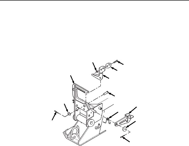
Remove cotter pin (Figure 4, Item 28), washer (Figure 4, Item 29), pivot latch (Figure 4, Item 11), and torsion
spring (Figure 4, Item 30) from pin lock guide (Figure 4, Item 6). Discard cotter pin.
36
35
37
6
34
33
32
11
30
29
31
28
Figure 4. BAP Front Pin Lock Assembly Disassembly.
10.
Remove cotter pin (Figure 4, Item 31), washer (Figure 4, Item 32), and headed straight pin (Figure 4, Item 33)
from pin lock jaw (Figure 4, Item 34). Discard cotter pin.
11.
Remove pin lock jaw (Figure 4, Item 34) from pin lock guide (Figure 4, Item 6).
12.
Remove two screws (Figure 4, Item 35), locknuts (Figure 4, Item 36), and wear pad (Figure 4, Item 37) from
pin lock jaw (Figure 4, Item 34). Discard locknuts.
NOTE
Measure the distance from the top of triangle-shaped weldment on top of pin lock bracket to
top of frame. Make a note of distance measured for later use during assembly.
13.
Remove two cotter pins (Figure 5, Item 38) from pin lock pin (Figure 5, Item 39). With the aid of an assistant,
remove two washers (Figure 5, Item 40) and pin lock pin (Figure 5, Item 39) from pin lock guide (Figure 5, Item
6). Discard cotter pins.
03/15/2011Rel(1.8)root(maintwp)wpno(M04047)